

Resistors are among the most fundamental components in electronics. Almost every circuit board, from smartphones to motor drives, contains dozens or hundreds of them. Despite their ubiquity, choosing the wrong resistor type for an application can lead to premature failures, thermal runaway, signal noise, and costly redesigns.
This is a complete guide for engineers and procurement buyers who need to understand the different resistor types and the tradeoffs between each one that can influence your sourcing decision.
What is a resistor? (The essentials)
A resistor is a passive electronic component that regulates or resists the flow of electrical current in a circuit. It does this by converting electrical energy into heat.
Resistance is measured in ohms (Ω). Values span from milliohms (mΩ) to gigaohms (GΩ).
The property is described by Ohm’s law: V = I x R, where V is voltage (volts), I is current (amperes), and R is resistance (ohms, Ω).
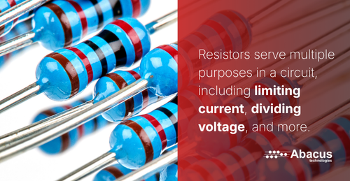
Resistors serve multiple purposes in a circuit, including:
- Limiting current: Protecting LEDs, transistors, and ICs from excessive current draw.
- Dividing voltage: Creating intermediate voltages for ADC references, biasing, and level shifting.
- Biasing: Setting the operating point of transistors and op-amps.
- Pull up/down: Defining logic-level states on data lines and I/O pins.
- Current sensing (shunts): Developing a measurable voltage drop proportional to current.
- Impedance matching: Maximizing power transfer in RF and transmission-line circuits.
- Filtering and timing: Forming RC time constants in filters, oscillators, and delay circuits.
Feedback networks: Setting gain and bandwidth in op-amp configurations.
Resistor type comparison: At a glance
| Type | Tolerance | TCR (ppm/°C) | Power Range | Noise | Inductance | Cost (Relative) | Best Application |
|---|---|---|---|---|---|---|---|
| Carbon Film | 5% | ±200 | 0.125–2 W | Medium-High | Low | $ | General-purpose, prototypes |
| Metal Film | 1% | ±50 | 0.125–0.6 W | Low | Low | $$ | Precision analog, audio, filters |
| Metal Oxide Film | 2–5% | ±200 | 0.5–5 W | Medium | Low | $$ | Power circuits, surge-prone designs |
| Thick Film SMD | 1–5% | ±100–200 | 31 mW–1 W | Medium | Very Low | $ | High-volume PCBs, general SMD |
| Thin Film SMD | 0.01–0.1% | ±5–25 | 31 mW–250 mW | Very Low | Very Low | $$$ | Precision, instrumentation, RF |
| Wirewound (std) | 0.1–5% | ±20–70 | 1 W–kilowatts | Low | High | $$–$$$ | Power loads, DC precision |
| Wirewound (non-inductive) | 0.1–1% | ±20 | 1 W–100+ W | Low | Low | $$$ | Audio power, precision power |
| Metal Foil | 0.001–0.01% | ±0.2–2 | 0.1–1 W | Extremely Low | Near Zero | $$$$ | Military, calibration, medical |
| Current Sense (Shunt) | 0.1–1% | ±5–50 | 0.5 W–10+ W | Low | Very Low | $$–$$$ | Power measurement, BMS |
Fixed resistor types
Carbon film resistors
Carbon film resistors are made by first depositing a thin carbon film on a ceramic rod. Then, a helix is cut into the film to increase the effective resistive path length and achieve the target value. They replaced carbon composition resistors as the standard general-purpose through-hole type.
Technical specifications:
- Typical tolerance: 5%
- Typical TCR: ±200 ppm/°C
- Power range: 0.125–2 W
- Value series: E24
Best for:
- Non-critical current limiting
- Pull-up/down networks
- Prototype builds
- Cost-sensitive high-volume consumer products with less precision
Avoid when:
- Low noise is essential
- Operating frequency exceeds ~1 MHz
- Temperature stability is pertinent
Metal film resistors
Metal film resistors deposit a nickel-chromium (NiCr) or similar alloy film onto a ceramic substrate. They offer significantly lower noise, better TCR, and tighter tolerances compared to carbon film. They’re the standard choice for precision analog designs.
Technical specifications:
- Typical tolerance: 1%
- Typical TCR: ±50 ppm/°C
- Power range: 0.125–0.6 W
- Value series: E96
Best for:
- Precision voltage dividers
- Op-amp feedback networks
- Filter circuits
- Instrumentation
- Audio circuitry
- Sensor interfacing
Avoid when:
- High power dissipation is needed
- Cost is the primary driver with no precision requirement
Procurement note: Abacus Technologies is an authorized distributor of VPG Foil Resistors, adding the industry's most stable and accurate Bulk Metal® Foil resistor technology to our line card. This includes VFR, Alpha Electronics, Powertron, and APR brands. Contact us for availability and pricing.
Thick film SMD resistors
Thick film resistors dominate modern PCB design because they are inexpensive, compact, and well-suited for automated assembly. A paste of resistive material is screen-printed onto an alumina (Al₂O₃) substrate and fired in a furnace, then laser-trimmed to value.
Technical specifications:
- Typical tolerance: 1–5%
- Typical TCR: ±100–200 ppm/°C3
- Power range: 31 mW – 1 W
- Value series: E24, E96
Best for:
- Any high-volume PCB design
- Automated SMT production
- Cost-sensitive designs
- General logic
- Computing
- Consumer electronics
Avoid when:
- Precision analog or low-noise designs (TCR of ±100–200 ppm/°C and tolerances of 1–5%) introduce too much drift and error for instrumentation
- High-frequency RF applications
- Avoid in extreme temperature environments
Thin film SMD resistors
Thin film resistors are manufactured by sputtering or vacuum-depositing an ultra-thin resistive alloy (typically NiCr or tantalum nitride) onto a substrate, then photolithographically patterning it to achieve precise values. While they are typically 5-15x more expensive than thick-film SMB resistors, the result is a device with dramatically better performance characteristics than thick film.
Technical specifications:
- Typical tolerance: 0.01–0.1%
- Typical TCR: ±5–25 ppm/°C
- Power range: 31 mW – 250 mW
- Value series: E96, E192
Best for:
- Precision instrumentation
- Medical devices
- ADC/DAC reference networks
- RF attenuators
- Test and measurement equipment
- Applications where long-term stability and low noise matter
Avoid when:
- Cost-sensitive, high-volume consumer designs
- High-power applications
Wirewound resistors
Wirewound resistors wrap a precision resistance wire (Nichrome, Manganin, or similar alloy) around a ceramic, fiberglass, or aluminum core. They are the go-to solution when high power dissipation, tight tolerance, and long-term stability are required simultaneously.
However, the coiled wire structure creates inductance that makes standard wirewound resistors unsuitable for AC or high-frequency applications. Non-inductive wirewound variants (bifilar wound) mitigate this, but cannot fully eliminate it.
Sourcing tip: For current-sense applications requiring low inductance at frequencies above 10 kHz, look for wirewound parts explicitly rated as "non-inductive" or consider switching to a low-inductance foil shunt resistor instead.
Technical specifications:
- Typical tolerance: 0.1–5%
- Typical TCR: ±20–70 ppm/°C
- Power range: 1 W – kilowatts
- Value series: E24, E96
Best for:
- Power load banks and dummy loads (1 W to several kilowatts)
- Precision laboratory resistors and current shunts
- DC motor drives and braking resistors
- Power supply ballast and inrush limiting
- Precision resistor networks where TCR matching between resistors matters
Avoid when:
- AC or high-frequency circuits
- Board space is critical
- High-volume automated assembly
Metal oxide film resistors
Metal oxide film resistors use a film of tin oxide (SnO₂) or similar oxide deposited on a ceramic substrate. They offer superior stability at elevated temperatures and can handle short-duration overloads better than carbon or metal film types. They are commonly used in applications where occasional voltage spikes or thermal stress is expected.
Technical specifications:
- Typical tolerance: 2–5%
- Typical TCR: ±200 ppm/°C
- Power range: 0.5 W – 5 W
- Value series: E24
Best for:
- Power supply circuits
- Surge-prone environments
- Automotive electronics
- Heating element controls
Avoid when:
- Precision work is necessary.
Metal foil resistors
Metal foil resistors represent the pinnacle of resistor technology, in which photolithographically-etched metallic foil (usually a nickel-chromium alloy) is bonded to a ceramic substrate. The result is performance characteristics that leave all other resistor types behind.
Technical specifications:
- Typical tolerance: 0.001–0.01%
- Typical TCR: ±0.2–2 ppm/°C
- Power range: 0.1 W – 1 W
- Value series: E96, E192
Best for:
- Military
- Aerospace
- Medical implants
- Wheatstone bridges
- Precision current sources
- Calibration standards
Avoid when:
- Cost is a primary constraint
- High-power applications
Variable resistors: Potentiometers and rheostats
Variable resistors allow the resistance value to be adjusted either by the user (panel-mounted pots) or during manufacturing/maintenance (trimmer pots). They are three-terminal devices: two fixed terminals connected to either end of the resistive track, and a third wiper terminal whose position determines the output resistance.
Types of variable resistors
- Panel potentiometers: Rotary or linear potentiometers with a shaft designed for user operation.
- Common in audio equipment (volume controls), lighting dimmers, motor speed controllers, and industrial control panels.
- Available in single-turn and multi-turn (10-turn) variants. Multi-turn pots provide much finer resolution.
- Trimmer potentiometers (Trimpots): Miniature potentiometers intended for one-time or infrequent adjustment by a technician with a screwdriver.
- Available in top-adjust and side-adjust configurations, through-hole and SMD. Used for offset nulling, gain calibration, and threshold setting.
- Rheostats: A two-terminal variable resistor where only one fixed end and the wiper are used.
- More common in high-power applications (motor starting resistors, lamp dimmers in older installations).
- Largely replaced by electronic controls in modern designs but still specified in legacy equipment.
Specialty resistor types
Resistor networks and arrays
Resistor networks package multiple resistors in a single component either as isolated individual resistors or with one shared common terminal. They are used where multiple identical resistors are required (data bus pull-ups, DAC ladders, LED current-limiting arrays) and where thermal matching between resistors is important.
Networks reduce board space, simplify assembly, and guarantee tighter resistance matching between elements than purchasing individual resistors. Common packages include SIP (Single Inline Package), DIP, and SOIC for SMD.
Current sense (shunt) resistors
Shunt resistors are precision, low-value resistors (typically 1 mΩ to 1 Ω) placed in series with a power rail to measure current. The voltage drop across the shunt (measured by a differential amplifier) is proportional to current.
Critical specifications include:
- Very low resistance value (to minimize power loss)
- Tight tolerance and low TCR (for accuracy across temperature)
- Low inductance (for accurate measurement at high switching frequencies)
- High power rating relative to value
- Four-terminal (Kelvin) connection to eliminate contact resistance error
Thermistors
Thermistors are resistors whose resistance changes significantly with temperature. NTC (Negative Temperature Coefficient) thermistors decrease in resistance as temperature rises and are widely used for temperature measurement and inrush current limiting. PTC (Positive Temperature Coefficient) thermistors increase in resistance with temperature and act as resettable self-limiting fuses in overcurrent protection circuits.
Varistors (MOVs)
Metal Oxide Varistors are non-linear resistors that clamp voltage transients. Their resistance is very high at normal operating voltages but drops sharply when voltage exceeds a threshold, diverting surge energy. They are essential in power supply input protection, equipment connected to AC mains, and anywhere lightning or switching transients are a concern.
Fusible resistors
Fusible resistors function as both a resistor and a fuse. Under normal conditions they operate as a standard resistor; under fault conditions (excessive current) they open circuit, protecting downstream components. Commonly found in power supply input stages and CRT monitor circuits.
High-voltage resistors
Standard resistors have a maximum voltage rating (typically 200–500 V) that can be exceeded in high-voltage power supplies, medical equipment, and industrial controls. High-voltage resistors use special construction and coatings to handle voltages from 1 kV to 100 kV or more.
How to choose the right resistor: Step-by-step framework
When specifying resistors, work through these parameters in order. Skipping any step risks a component that meets the nominal spec but fails in the application.
- Define the required resistance value and series: Calculate your target value using Ohm's Law and circuit analysis. Then check whether your exact value falls in the E24 (5%), E96 (1%), or E192 (0.1–0.5%) series, or if you'll need a precision custom value. Most circuits can be designed around standard series values.
- Calculate the required power rating, then derate: Use P = I²R or P = V²/R to find the maximum power dissipation. Then select a resistor rated for at least 2× to 3× that power (50% derating is an industry standard minimum; go to 33% derating for high-reliability designs). Operating a resistor at its rated power significantly shortens its life and increases drift.
- Determine the required tolerance: Only specify the tolerance your circuit actually needs. A pull-up resistor typically works fine with 5%; an op-amp gain-setting resistor may need 1%; a precision voltage reference divider may require 0.1% or better. Over-specifying tolerance adds cost without benefit; under-specifying causes performance issues.
- Evaluate TCR against your operating temperature range: Multiply the expected temperature swing (ΔT) by the TCR. For example, a ±100 ppm/°C resistor over a 60°C range drifts ±0.6%. This may be acceptable or may not, depending on the circuit. If drift matters, step up to thin film.
- Check the voltage rating: Small SMD resistors (0402, 0603) often have maximum working voltages of 50–100 V. In high-voltage designs, this is commonly overlooked. Verify the resistor's max working voltage and pulse voltage against your circuit's actual voltage, including transients.
- Consider frequency and inductance: For applications above 100 kHz, the inductance and parasitic capacitance of the resistor become relevant. Wirewound resistors are generally unsuitable for AC without non-inductive winding. Thin-film SMD resistors have the best high-frequency behavior.
- Select package and mounting style: SMD (0402/0603/0805) for automated assembly; through-hole for prototyping, high-power applications, and designs requiring manual soldering. Confirm the package matches your PCB footprint and reflow profile.
- Verify environmental and compliance requirements: Does the application require AEC-Q200 (automotive), MIL-PRF qualification, RoHS compliance, or halogen-free materials? These qualifications narrow the approved supplier list significantly and should be confirmed early in sourcing.
Other resistor sourcing considerations
For procurement teams and engineers involved in component sourcing, understanding the supply chain landscape for resistors is just as important as understanding the technical specifications.
- Approved Vendor List (AVL) management: For production designs, qualify 2–3 approved manufacturers per resistor type to ensure dual-sourcing. Passive components are frequently the source of supply chain disruptions.
- Minimum Order Quantities (MOQs): High-precision or specialty types (foil, high-voltage, AEC-qualified) often have higher MOQs and longer lead times. Factor these into your NPI timeline.
- Date codes and shelf life: Resistors have no expiration date per se, but older stock may have oxidized terminations affecting solderability. Request current date codes for production orders.
- Qualification standards: Automotive designs require AEC-Q200 qualification. Military and aerospace often require MIL-PRF-55342 (film) or MIL-PRF-39007 (wirewound). Confirm qualification before adding to the BOM.
- RoHS and REACH compliance: Verify that parts are fully compliant with current EU directives, particularly if end products are sold in Europe or California (Proposition 65).
- Tape and reel vs. cut tape vs. bulk: SMD resistors are packaged in tape-and-reel (full reels of 5,000–10,000 parts) for automated assembly. Cut tape is available for lower quantities. Confirm the package type matches your pick-and-place equipment.
- Counterfeit risk management: Resistors, particularly precision and military types, are a target for counterfeit components. Source from franchised distributors or direct from manufacturers for high-reliability applications. Abacus Technologies sources only from authorized channels with full traceability.
- Equivalent part cross-referencing: When a specified part is unavailable, a cross-reference must be carefully validated. TCR, operating temperature, case dimensions, and land pattern must also be considered.

Resistor color code: Quick reference
Through-hole resistors are marked with color bands that encode their resistance value, tolerance, and sometimes TCR. Four-band resistors encode two significant digits; five-band and six-band resistors encode three significant digits (higher precision).
Directions: Read from the end with the band closest to a lead. The tolerance band (gold or silver) is typically on the right-hand side. For a four-band resistor: Band 1 = first digit, Band 2 = second digit, Band 3 = multiplier, Band 4 = tolerance.
| Color | Digit Value | Multiplier | Tolerance (4th band) |
|---|---|---|---|
| Black | 0 | ×1 | — |
| Brown | 1 | ×10 | ±1% |
| Red | 2 | ×100 | ±2% |
| Orange | 3 | ×1 kΩ | — |
| Yellow | 4 | ×10 kΩ | — |
| Green | 5 | ×100 kΩ | ±0.5% |
| Blue | 6 | ×1 MΩ | ±0.25% |
| Violet | 7 | ×10 MΩ | ±0.1% |
| Grey | 8 | — | ±0.05% |
| White | 9 | — | — |
| Gold | — | ×0.1 | ±5% |
| Silver | — | ×0.01 | ±10% |
Example resistor band calculation
- Band 1: Yellow
- Meaning: 1st significant digit
- Value: 4
- Band 2: Violet
- Meaning: 2nd significant digit
- Value: 7
- Band 3: Red
- Meaning: Multiplier
- Value: x100
- Band 4: Gold
- Meaning: Tolerance
- Value: ± 5%
Calculation: 47 × 100 = 4,700 Ω, ±5%
SMD resistor marking codes
SMD resistors use numerical or E96 alphanumeric codes because the components are too small for color bands.
Three-digit code (Standard tolerance)
Format: XYZ where XY = first two significant digits, Z = number of zeros.
Example: 472 = 47 × 10² = 4,700 Ω (4.7 kΩ).
Four-digit code (1% tolerance)
Format: XYZW where XYZ = three significant digits, W = number of zeros.
Example: 4702 = 470 × 10² = 47,000 Ω (47 kΩ).
E96 code (1% precision SMD)
Format: Uses a two-digit code (01–96) mapping to the E96 value table, followed by a letter indicating the multiplier.
Example: 01A = 100 Ω × 1 = 100 Ω; 68C = 499 × 100 = 49.9 kΩ. An E96 lookup table is required to decode these.
Matching the right resistor to the right application
Resistors are deceptively simple components. Selecting the wrong technology, underrated power, insufficient tolerance, or mismatched TCR is a leading cause of field failures and costly redesigns. The key principle is this: always select based on what the application actually demands, not just the nominal resistance value.
For most general-purpose PCB designs, thick-film SMD resistors in 0402 or 0603 offer the best balance of cost, size, and performance. Step up to thin-film when precision or noise matters. Use wirewound when high power is required in DC applications. Reserve metal foil for the highest-precision requirements where budget is not the primary constraint.
On the sourcing side, always dual-source critical values, confirm qualification standards early, and work with a trusted distributor who can provide full component traceability and counterfeit risk mitigation.
Abacus Technologies specializes in sourcing passive components including the full range of resistor types across commodity and specialty categories. As an authorized VPG Foil Resistors distributor, we stock the industry's most precise Bulk Metal® Foil resistor technology across the VFR, Alpha Electronics, Powertron, and APR brands. Our team provides technical cross-reference support, compliance documentation, and flexible inventory programs for both prototype quantities and high-volume production.
Resistor frequently asked questions (FAQs)
What is the difference between a potentiometer and a rheostat?
Both are variable resistors. A potentiometer uses all three terminals (two ends + wiper) as a voltage divider. A rheostat uses only two terminals (one end + wiper) as a variable series resistor. The same physical component can often be wired as either, but rheostats are typically higher-power devices.
Can I use resistors in parallel or series to get a value not available in the e-series?
Yes, this is a common design technique. Two resistors in series simply add their values (R_total = R1 + R2). Two resistors in parallel give R_total = (R1 × R2) / (R1 + R2). Combining two E96 resistors gives access to essentially any value, though this occupies more board space and adds assembly cost.
What is power derating and why is it important?
Power derating means operating a resistor at less than its maximum rated power, typically 50–70%, to extend its lifetime and ensure reliable operation at elevated ambient temperatures. Most power ratings are specified at 70°C ambient; at higher temperatures, the allowable power decreases. Operating a resistor continuously at 100% of its power rating causes accelerated aging, resistance drift, and eventual failure.
What does "1206" or "0603" mean on a resistor?
These are standard SMD package size codes in the imperial system. The four digits represent dimensions in hundredths of an inch: 0603 = 0.06 inches × 0.03 inches (1.6 mm × 0.8 mm). The equivalent metric code for the same package would be 1608. Always confirm which system (imperial/metric) your distributor or datasheet is using, as a metric 0603 and an imperial 0603 are different sizes.
What is the difference between thick film and thin film resistors?
Thick film resistors are made by screen-printing a paste containing resistive particles (typically ruthenium oxide compounds) onto a ceramic substrate and firing it. The resulting film is 10–50 µm thick. Thin film resistors use vacuum sputtering or evaporation to deposit a metallic alloy film that is less than 1 µm thick. Thin film offers dramatically better TCR, tolerance, and noise performance at higher cost.
When should I use a resistor network instead of individual resistors?
Use a resistor network when you need multiple resistors of the same value (pull-up arrays, data bus termination, LED drivers) and benefit from guaranteed resistance matching between elements, reduced board area, and a single BOM line item. Networks are particularly valuable when thermal matching matters. Since all resistors share the same substrate, they track temperature identically.
Are all resistors RoHS compliant?
No, not all resistors are automatically RoHS compliant. Older wirewound types and some specialty resistors may use lead-containing materials. Always verify compliance status on the manufacturer's datasheet or compliance declaration before specifying for EU or California-regulated markets. Most modern SMD resistors from major manufacturers are RoHS compliant, but always confirm explicitly.